Tuesday, February 21, 2017

Multilevel inverter (5 level) based variable frequency drive


Concept:


Important parts :


            1. Induction motor (0.5hp, 230V, 1.5A)

            2. Mosfets / IGBTs based on the machine voltage and current ratings.
            3. No. of  DC power supplies (depends on no. of levels).
                               Two power supplies - two mosfet bridges for 3 level
                               Four power supplies - four mosfet bridges for 5 level

            4. Each power supply consists of a rectifier bridge, filter capacitor and a fuse.
            5. Each power supply will be conncetd to the MOSFET bridge.
            6. The MOSFET bridges should be coonected to the power supplies.(The following Figure is for 9 level)
            7. 89s52 microcontroller is programmed in my project according to the switching logic of
                Cascaded inverter.

            8. The signals from MC will be given to the mosfet bridges through the optocoupler unit.
            9. Optocoupler unit requires seperate power supplies. A multiwinding transformer is used in
                my project to excite the optocoupler transistor.

We have re-wound the transformer as per our requirements. We just disassembled a transformer and calculated the number of turns required and then fixed it back.


We have done an experiment to see the stress experienced by the switches for the 0.5hp induction motor. We build a capacitor based potential divider to design diode clamped inverter. The diode clamped inverter is my next project and probably it will be a three phase drive.


This multilevel inverter is tested with a resistive load. Two transformers are used as the main power supplies. each 12V. The filtered output gave 18V for each bridge. The three levels are 0v 18v 36v.


Monday, March 10, 2014

Tower Pro Micro servo 99 sg90 control

Tower Pro Micro servo 99 sg90 control. 


The inbuilt controller of servo is already programmed with a closed loop control system using a pot. All that required is to give a pulse train with 5% to 10% duty cycle with 20ms as period.


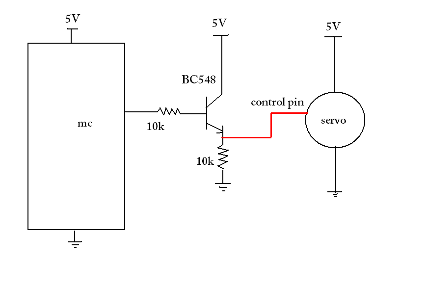
 Most schematics on the internet shows a direct connection between micro controller and servo control pin. That is not correct.


It is required to use a buffer/ current driver for the servo. Use a transistor to connect control pin to micro controller.


The code:

#include<reg52.h>
sbit servo_pin = P1^0;
void delay(unsigned int);
void main()
{
int k,i=0,a[4]={6,12,21,12};
 pin = 0;
while(1)
{
for(k=0;k<100;k++)
{
servo_pin=1;
  delay(a[i]); // a[i] is Ton period  (Ton is precalculated)
  servo_pin=0; // The array a[i] values are calculated to stop the motor at 0, 90 and 180 degrees
  delay(200-a[i]);        //200 represents 20ms(i.e., 200x0.1ms)
}                 //200-a[i] is Toff(=T-Ton=20-Ton)
i++;
if(i==4)
i=0;
}
}

void delay(unsigned int ms)   \\ delay for 0.1ms (tested on oscilloscope)
{
int i,j;
for(i=0;i<ms;i++)
for(j=0;j<11;j++);
}


Thursday, June 27, 2013

Thyristor controlled capacitor


Thyristor controlled capacitor. It is a static VAR compensator designed to make unity power factor operation of a three phase induction motor.

I have used two microcontrollers for this project. One is to measure the time difference between the zero crossing points of voltage and line current. The second one is to generate three phase pulse trains to fire three phase AC voltage controller. A star connected capacitor bank is used as a reactive power source. Depending on the time gap (phase angle difference), the capacitors are charged at the controlled rate.


Zero Crossing Detectors (ZCD) for voltage and line currents


The ports of Thyristor controlled capcitor


Sunday, March 10, 2013

My work bench (my favorite place).....

This is my first post in this blog.
I want to share my work bench photos here.
My pc (AMD athlon 64 4000+ , GTS40) is connected to acer 18." monitor and samsung 37" LCD. My iPad 2 is connected to the pc through 'logmein'.

my DIY power supply


power supply specification: +15v 0 -15v
0 - 30V variable, 750 mA

My component box


My work bench


Solar Car

Solar Powered Electric Car Specifications: 1. Solar Panels -----  3 x 120W 2. BLDC Motor ------ 48v, 3KW  3. BLDC Motor Contro...